.bmp)

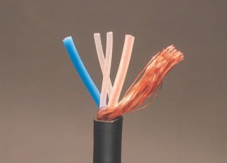
Spiral Shield Wire
All the concepts in the AWG are explained like this more than once, in fact, so you can follow along easily and understand every point. And the illustrations will show you exactly what I ’ m talking about.
There are two other common types of wire: these are spiral shield wire and braided shield wire. They do the exact same thing as the mylar foil shielded wire in Figure 1.1 , but the shield construction is different.
In spiral shield wire ( Figure 1.3 ), the shield layer is actual strands of copper, wound in a spiral around the inner conductors. The two inner conductors here are the blue and the translucent-over-copper colored items in the picture. The two thinner pale white strands have no electrical function, they are ‘ packing strands ’ that help keep the wire round when it ’s made.
This type of wire is stronger and more noise-resistant then the mylar shield type in Figure 1.1 , but it ’s also larger and costs more. It ’s fl exible and fast to work with, as opposed to the next type of wire I want to discuss.
Braided shield wire offers top notch shielding, and it ’s very durable. But it ’s a real pain to work with, because you have to carefully unbraid the shield to connectorize it. Not recommended for the impatient.
Still with me? The three types of wire I ’ ve shown you all do the same thing, but they look different, require different techniques, and offer different pros and cons in terms of use. I ’ m showing all of them to you, because you ’ re likely to encounter all of them in your wiring saga.
A lot of wiring work is like the examples above; the diversity of options available make it seem complicated and confusing. The trick is to see the underlying unity among the options. Three kinds of wire all do the same thing – cool!
If you ever do get confused, just stop, back up a page and read it over which is a lot easier than hoping for the best, doing it wrong and doing it over. Take your time, and the AWG will soon have you soldering like a pro.
Other terms used in this section are explained the fi rst time they are used in the text. If you skip a section where a defi nition is given, or if you forget it, you can look it up in the online glossary we ’ ve added to the AWG website.
We (Focal Press and myself) chose to keep the glossary on the web in order to update it, and to allow more space in the book itself for vital information.
Some sections of the book (like the soldering instructions) are written with deliberate redundancy. If I tell you how to wire a connector, I have to give all the steps in the proper sequence. If you have to fl ip back and forth in the book to see how a connector is wired, it will only slow you down. So each connector section is designed to be read and followed as a piece of standalone text.
A caution, however: the illustrations show the ground wire always connected, since this is how an individual cable would be wired. A star-grounded system would have ground connected at only one end, not both (star grounding is thoroughly covered in a later chapter).
However, be sure you understand the concept of star grounding before doing work on previously installed wiring or starting construction of a new system. The difference in a star-grounded system is that the shield (ground) wire is connected at only one end, rather than both. Connecting shield at both ends of a wire can cause ‘ ground loops ’ , which induce ‘ hum ’ and other types of noise in audio systems. Star-ground installations are always customwired
and therefore costly – but they radically reduce system noise.
.bmp)


0 comments:
Post a Comment